
|
|
|
|
|
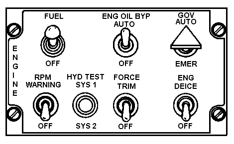
The pilot FUEL switch FUEL position energizes the forward and aft boost pumps, opens the fuel shutoff valve, and completes the ignition and start fuel circuit. The aft fuel boost pump circuit is powered by the dc nonessential bus. The other circuits are powered by the dc essential bus. The circuits are protected by the START RLY, IGN SOL, FUEL/OIL VALVE, FUEL BOOST FWD, and FUEL BOOST AFT circuit breakers.
The pilot ENG OIL BYP switch AUTO position permits the oil to automatically bypass the oil cooler when the oil tank is approximately 3.8 quarts low. The OFF position deactivates the automatic bypass feature causing the oil to pass through the oil cooler regardless of the oil tank level. The switch circuit is powered by the dc essential bus and is protected by the FUEL OIL VALVE circuit breaker.
The pilot or gunner GOV switches AUTO position permits the overspeed governor to automatically control fuel metering and engine speeds (N1and N2). The EMER position permits the pilot and gunner to manually control the engine rpm. The governor circuit is powered by the dc essential bus and protected by the GOV CONTR circuit breaker.
The RPM WARNING switch OFF position prevents audio warning from functioning when the audio might be objectionable. The switch automatically resets to WARNING position when the engine and rotor reach normal rpm.
The pilot HYD TEST switch is used to test the NO. 1 and NO. 2 hydraulic systems. Holding the switch in the SYS 1 position will cause the NO. 1 system to be the only system supplying hydraulic pressure. Similar action occurs when the switch is held in the SYS 2 position.
Force Trim System: The system incorporates a magnetic brake and force gradient in the cyclic and directional control systems to provide artificial feel into the systems. Also, it provides a means to trim the controls. Placing the FORCE TRIM switch in the FORCE TRIM position will induce artificial feel into the systems. Depressing the cyclic stick force trim switch will cause the magnetic brake and force gradient to be repositioned to correspond to the positions of the cyclic stick and pedals thus providing trim. The system is powered by the dc essential bus and protected by the FORCE TRIM circuit breaker.
Engine Inlet Anti-icing/ Deicing System: The system prevents ice from forming in the engine air inlet. The system consists of a hot air solenoid valve on the engine, controlled by the pilot or gunner ENG DEICE switch, powered by the dc essential bus, and protected by the ENG DEICE circuit breaker. If ice accumulation is suspected, the pilot or gunner ENG DEICE switch is placed in the DEICE position. This action causes the hot air solenoid valve to route engine bleed air to the engine air inlet. A rise in the turbine gas temperature (TGT) will occur when the pilot or gunner ENG DEICE switch is in the DEICE position. De-ice operations will become continuous if the hot air solenoid valve (ENG DEICE) circuit fails or if ENG DEICE circuit breaker is out (extended).
|
|
|
|
| Updated: 12 January 2008 |
|
Born on 20 March 1999 |